Thank you for visiting SNEWPapers!
Sign up free
Story
October 5, 1922
Emmons County Record
Linton, Williamsport, Emmons County, North Dakota
What is this article about?
Instructional article on substituting a three-electrode vacuum tube for a crystal detector in a simple radio receiving set to obtain louder signals, including required materials, connection tips, adjustments for filament current and plate potential, and warnings about battery polarity and tube overload.
Clipping
OCR Quality
85%
Good
Full Text
RADIO
CHANGE POTENTIAL
TO OBTAIN SIGNALS
Way in Which This May Be Done
With Three-Electrode
Vacuum Tube.
[A three-electrode vacuum tube can
be substituted for the crystal as a detector
in the simple radio receiving
set described in this column a short
time ago. Using a vacuum tube in
place of a crystal detector will give
a much louder signal, and a detector
that when once adjusted will stay adjusted.
The material which will be
required to do this is as follows:
One standard vacuum socket.
One 6-10 ohm filament rheostat.
One grid condenser and leak combined.
A source of filament current and a
source of plate potential.]
Element leads in connecting a socket
will be disastrous to the life of the
filament.
Note that the filament rheostat is
set to place the maximum amount of
resistance in series with the filament.
After inserting the tube see that it is
properly seated and that the four
prongs protruding from the tube base
make good contact with their respective
contacts in the tube socket.
If, after listening in with a vacuum
tube used as a detector with a rated
filament current and plate potential,
no signals are heard, go over the circuit
carefully and inspect all connections,
contacts, polarity of both the
"A" and "B" batteries, and take a look
at the grid condenser and leak.
For every filament current there is
a definite plate potential that will
give the strongest signals. When using
fairly hard tubes - high vacuum -
bringing out taps from the individual
cells of the plate or "B" battery will
give variations that are fine enough.
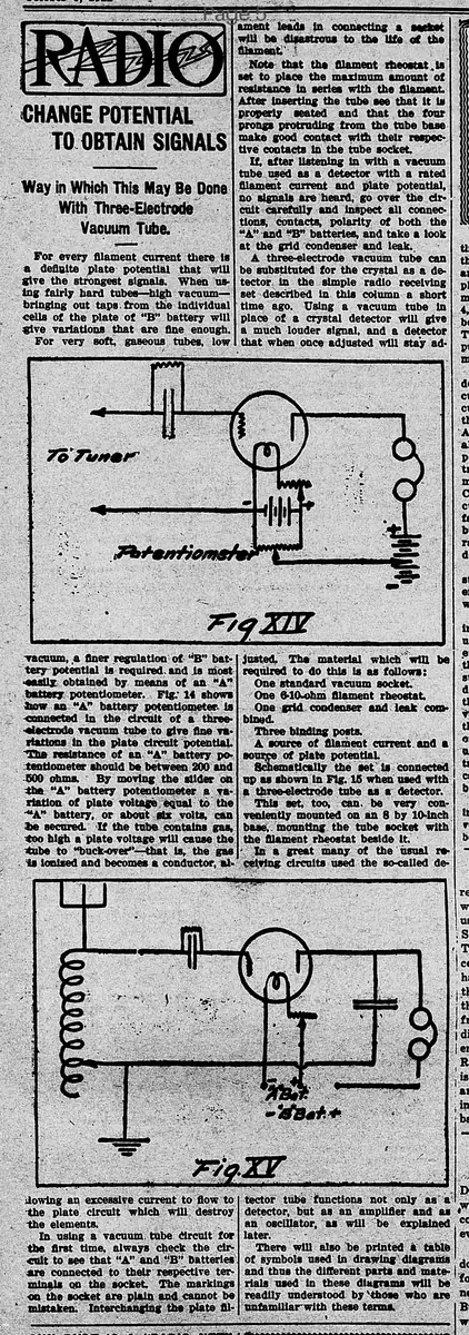
For very soft, gaseous tubes, low
vacuum, a finer regulation of "B" battery
potential is required, and is most
easily obtained by means of an "A"
battery potentiometer. Fig. 14 shows
how an "A" battery potentiometer is
connected in the circuit of a three-
electrode vacuum tube to give fine variations
in the plate circuit potential.
The resistance of an "A" battery potentiometer
should be between 200 and
500 ohms. By moving the slider on
the "A" battery potentiometer a variation
of plate voltage equal to the
"A" battery, or about six volts, can
be secured. If the tube contains gas,
too high a plate voltage will cause the
tube to "buck-over" - that is, the gas
is ionized and becomes a conductor, allowing
an excessive current to flow to
the plate circuit which will destroy
the elements.
In using a vacuum tube circuit for
the first time, always check the circuit
to see that "A" and "B" batteries
are connected to their respective terminals
on the socket. The markings
on the socket are plain and cannot be
mistaken. Interchanging the plate filament
CHANGE POTENTIAL
TO OBTAIN SIGNALS
Way in Which This May Be Done
With Three-Electrode
Vacuum Tube.
[A three-electrode vacuum tube can
be substituted for the crystal as a detector
in the simple radio receiving
set described in this column a short
time ago. Using a vacuum tube in
place of a crystal detector will give
a much louder signal, and a detector
that when once adjusted will stay adjusted.
The material which will be
required to do this is as follows:
One standard vacuum socket.
One 6-10 ohm filament rheostat.
One grid condenser and leak combined.
A source of filament current and a
source of plate potential.]
Element leads in connecting a socket
will be disastrous to the life of the
filament.
Note that the filament rheostat is
set to place the maximum amount of
resistance in series with the filament.
After inserting the tube see that it is
properly seated and that the four
prongs protruding from the tube base
make good contact with their respective
contacts in the tube socket.
If, after listening in with a vacuum
tube used as a detector with a rated
filament current and plate potential,
no signals are heard, go over the circuit
carefully and inspect all connections,
contacts, polarity of both the
"A" and "B" batteries, and take a look
at the grid condenser and leak.
For every filament current there is
a definite plate potential that will
give the strongest signals. When using
fairly hard tubes - high vacuum -
bringing out taps from the individual
cells of the plate or "B" battery will
give variations that are fine enough.
For very soft, gaseous tubes, low
vacuum, a finer regulation of "B" battery
potential is required, and is most
easily obtained by means of an "A"
battery potentiometer. Fig. 14 shows
how an "A" battery potentiometer is
connected in the circuit of a three-
electrode vacuum tube to give fine variations
in the plate circuit potential.
The resistance of an "A" battery potentiometer
should be between 200 and
500 ohms. By moving the slider on
the "A" battery potentiometer a variation
of plate voltage equal to the
"A" battery, or about six volts, can
be secured. If the tube contains gas,
too high a plate voltage will cause the
tube to "buck-over" - that is, the gas
is ionized and becomes a conductor, allowing
an excessive current to flow to
the plate circuit which will destroy
the elements.
In using a vacuum tube circuit for
the first time, always check the circuit
to see that "A" and "B" batteries
are connected to their respective terminals
on the socket. The markings
on the socket are plain and cannot be
mistaken. Interchanging the plate filament
What sub-type of article is it?
Technical Instruction
How To Guide
What keywords are associated?
Vacuum Tube
Radio Detector
Filament Rheostat
Plate Potential
Battery Potentiometer
Signal Adjustment
Story Details
Story Details
Describes substituting a three-electrode vacuum tube for a crystal detector in a radio set for louder signals; lists materials; explains connections, adjustments for filament and plate potentials, battery polarities, and risks like tube overload from high voltage.